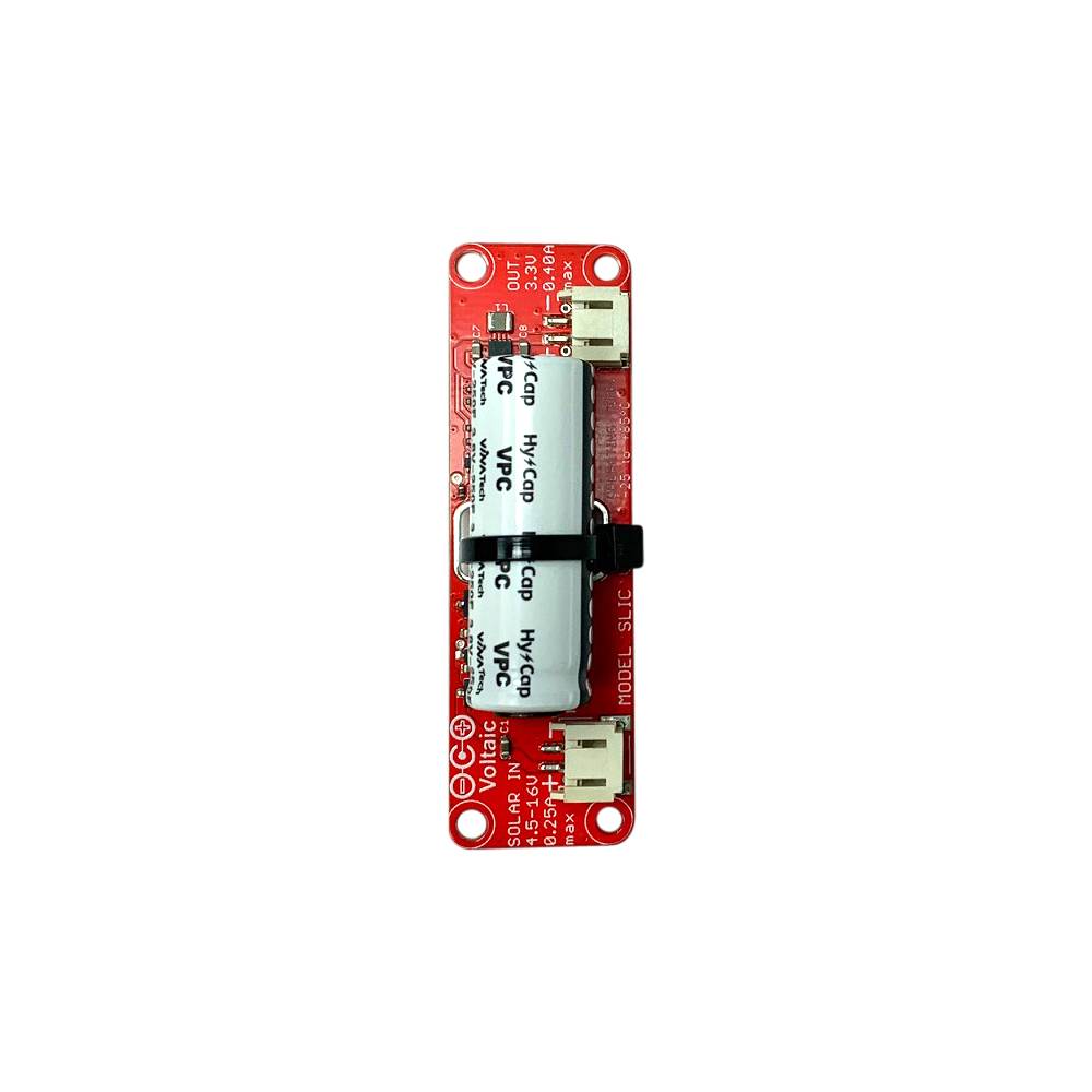
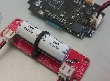
This tutorial will show you how to power the Generic Node Sensor Edition using the Voltaic Lithium-Ion Capacitor Solar Charger, which includes a 250F Lithium-Ion Capacitor for power storage and a Linear regulator (C116). The solar charger outputs an unregulated 2.5V - 3.8V, which is sufficient for powering the Generic Node Sensor Edition as it accepts a range of input voltages from 2.2V to 5.5V.
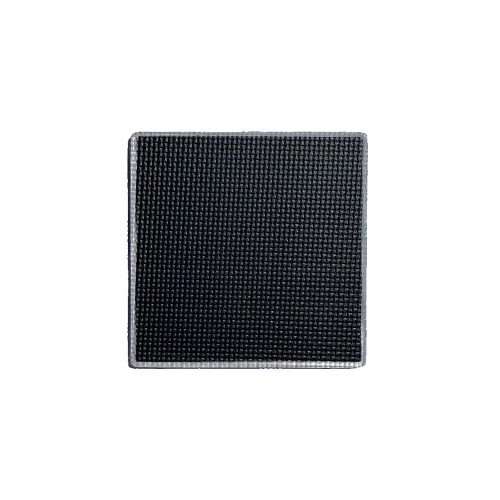
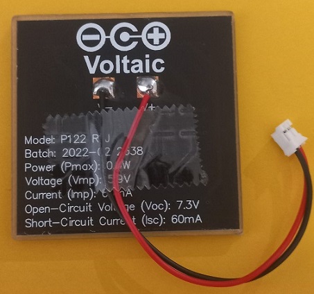
Additionally, you will need a 0.3W 6V Mini Solar Panel - ETFE to work with the solar charger.
Take a 2-pin JST (female) cable. Solder its wires to the Voltaic mini solar panel, ensuring that the negative and positive wires are correctly attached to the corresponding pads.
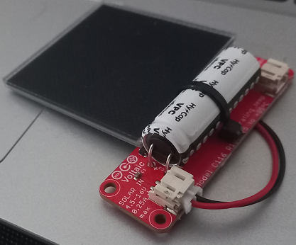
Connect the female JST connector of the mini solar panel to the male JST connector marked as ‘IN’ on the solar charger.
Note:
Using a multimeter, check the voltage at the JST connector on the solar charger marked as ‘OUT’. If the output voltage is below 2.5V, leave the mini solar panel under sunlight for some time to charge the supercapacitor.Take another cable with female JST 2-pin connectors at both ends. Connect one end to the universal power input JST connector marked as ‘BATTERY’ on the Generic Node Sensor Edition and the other end to the JST connector marked as ‘OUT’ on the Voltaic Lithium-Ion Capacitor Solar Charger.
The Generic Node Sensor Edition will be powered by the solar power stored in the supercapacitor.
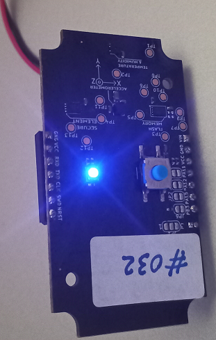
Program your Generic Node Sensor Edition with one of our sample applications, and then connect it to The Things Stack.
Verify that the messages sent from the Generic Node Sensor Edition are received on The Things Stack side.