Follow this section to learn to program executables to your Generic Node Sensor Edition with the ST-LINK programmer.
ST-LINK
The ST-LINK debugger and programmer is required to program the Generic Node Sensor Edition. There are multiple versions of this probe, but most of them have a similar pin-out and functionality. In this guide, we will be using the ST-LINK/V3SET probe. Commonly used ST-LINK probes feature blinking LEDs to indicate the programming process.
Wiring your ST-LINK to the Generic Node Sensor Edition
The wiring from the ST-LINK/V3 programmer → Generic Node Sensor Edition is as follows:
- VCC → VCC
- GND → GND
- CLK → CLK
- DIO → SWD
- NRST → NRST
Optionally you can connect RX and TX pins to work with UART (either for sending and receiving messages or programming).
- RX → RX (Only with ST-LINK boards, other boards would be RX → TX)
- TX → TX (Only with ST-LINK boards, other boards would be TX → RX)
Warning:
Be careful not to mix VCC with VIN pin on the Generic Node Sensor Edition. VIN should still be powered separately, either with the pin or the battery connector, as it powers the Generic Node Sensor Edition. VCC is used as target voltage indicator.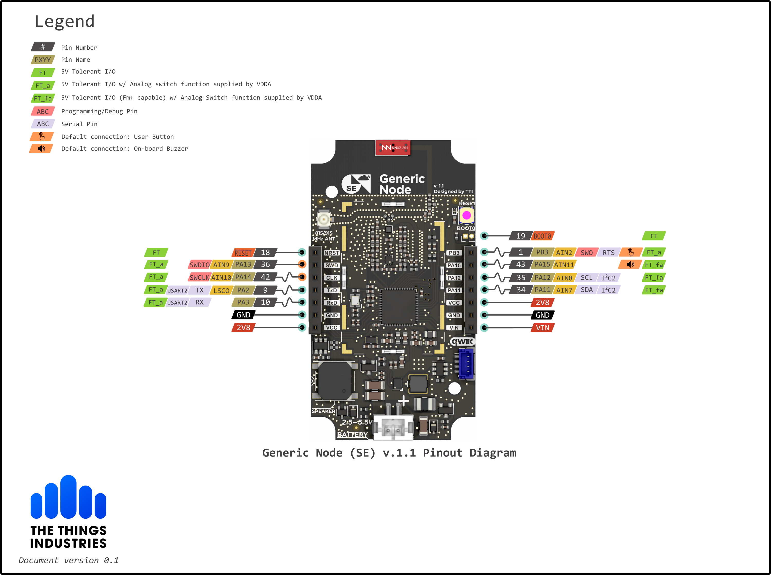
When you are done with the setup, visit the ST-LINK Programming Methods section to choose and follow a guide using a development tool that best fits your preferences. Then you can also check out the Applications section for application examples.